
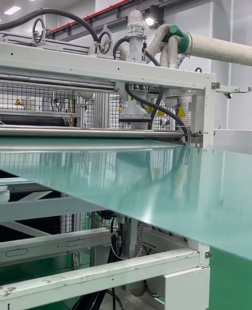
PC PMMA Film can provide a clear decorative substrate, yet a smooth incoming sheet may show adhesive lines or support patterns after mounting. The defect can remain visible even when the bond contains no obvious bubbles. Before replacing the optical material, determine whether the pattern is seen through the panel or has physically distorted its viewing surface.
Dafu's engineering film range supplies PC/PMMA film and sheet made by co-extrusion, with transparent, printable surfaces for decorative processing. Buyers can choose among different product categories and finishes. These descriptions support selecting a panel substrate. They do not establish that every adhesive geometry or rear carrier will remain invisible through every gauge and artwork design.
Identify the kind of read-through
Inspect the panel in reflected light and, where the design allows it, in transmitted light. A visible adhesive color or outline may be an optical concealment issue. A ripple that changes the reflected image can indicate local shape variation. Both can appear as a bond pattern, but they call for different investigations.
Mark the pattern relative to tape borders, adhesive beads, carrier ribs and attachment points. A repeating pattern matching the rear construction provides a useful clue. Keep an unmounted reference beside the assembly so the team can distinguish incoming waviness from a change introduced during bonding.
Do not classify every visible patch as trapped air. Bubbles and incomplete contact remain possible, but a continuous line following a support rib may involve another mechanism. Record the observed appearance before reworking the sample so the original relationship between the mark and rear structure is preserved.
Map the full decoration and support arrangement
Draw the viewing face, composite orientation, printed layers, adhesive and carrier. Identify which areas are opaque, translucent or intentionally clear. The same rear feature may be hidden beneath dense artwork and visible in a light-colored or transparent region, making the artwork part of the assessment.
Confirm the intended PC and PMMA side orientation with the converter. Bonding and decoration should follow the selected construction, rather than changing faces during a trial to improve one observation. A sample assembled in a different orientation is a different optical and mechanical comparison.
Include the real carrier surface where practical. A flat laboratory backing may not reproduce molded ribs, recesses or local stiffness in the final part. If a simplified support is used for screening, state which features it represents and what remains to be tested on the production geometry.
Separate adhesive visibility from panel deformation
For an optical issue, compare the adhesive's appearance behind representative print coverage and panel thickness. A nominally transparent adhesive can still differ from an air gap or another surrounding region in the assembled view. Evaluate the visual boundary directly instead of approving the adhesive from a separate clear coupon.
For a shape issue, investigate the bond distribution and the way the panel is supported during attachment. A narrow adhesive line or a local fixture force can produce a different load pattern from a broad bonded area. Treat these as trial variables, not proof that a particular adhesive format is always unsuitable.
Where the adhesive develops or cures after assembly, record that history and review its behavior with the supplier. Do not assume a universal shrinkage value or attribute every ripple to cure contraction. Compare the panel before bonding, after fixture release and after the relevant conditioning to locate when the change appears.
Use thickness and stiffness as design variables
A thinner panel may follow local rear features more readily, while a thicker design can change fit, forming requirements and overall appearance. Compare proposed gauges within the product's confirmed supply options. The objective is a balanced component, not simply the thickest film that hides a trial defect.
If the panel is formed, assess the actual formed part. Local section and geometry can differ from a flat reference, and the support may contact curved regions unevenly. A flat adhesive trial remains useful for screening but should not establish the entire bond pattern for a shaped component.
Review carrier flatness and attachment tolerance alongside the film. A material change may mask one prototype's variation without controlling the underlying support problem. The accepted design should identify which dimensions and contact conditions production needs to maintain, rather than relying on the panel to accommodate any rear geometry.
Inspect under lighting that reveals the customer complaint
Use a defined viewing distance, angle and light arrangement relevant to the finished product. Oblique reflected light can help locate waviness, while the normal installed view determines whether the feature is unacceptable. Keep investigative lighting and release criteria distinct so the test remains both sensitive and meaningful.
Compare the same assemblies under the agreed conditions after relevant thermal and storage exposure. A newly bonded part and one that has relaxed or aged may not look identical. Record when each inspection occurs and retain photographs tied to the sample's process history.
Include decorative reference regions near the bond pattern. A glossy dark surface can reveal a distorted reflection differently from a textured or patterned area. Changing artwork may be a design option, but it should be approved as such rather than used to conceal an unresolved structural issue without discussion.
Approve the bond function and appearance together
An attractive panel still needs the required attachment strength and durability. A stronger attachment is equally incomplete if its rear pattern violates the product's appearance requirement. Evaluate those outcomes on the same construction so separate approvals do not accidentally refer to different adhesive layouts.
Send Dafu and the converter a cross-section, intended gauge, artwork and photographs showing the mark relative to the rear support. Ask for representative sample material to compare selected bond layouts. PC/PMMA composite film can remain suitable while the attachment design needs refinement. The useful result is a decorative panel whose accepted appearance survives assembly and conditioning, with a bond arrangement that production can reproduce without visible lines or unwanted surface distortion.