
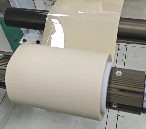
PEEK film considered for a formed insulating liner must be selected against the thinnest finished region, not only the starting sheet gauge. A liner can fit the housing and look intact while a corner has stretched more than the surrounding wall. If the project needs electrical separation through that corner, appearance and overall dimensions are not sufficient acceptance checks.
Dafu's engineering plastic film manufacturer range lists DFPK-G PEEK for electrical insulation, with several surface finishes. The product page provides material information for flat film. A formed-liner project adds geometry and processing requirements that need a separate trial. Confirm that the proposed grade and gauge are appropriate for the forming route before treating the flat-film information as finished-part evidence.
Start with the location that needs protection
Identify the conductors, housing edges and contact points that the liner will separate. Mark the regions where electrical clearance or material coverage is most critical. The deepest drawn region is not always the controlling location; a mounting hole or a corner touching a metal edge may matter more. The material selection should follow this functional map rather than a uniform-wall assumption.
Show the expected installed shape, including overlaps and trimming boundaries. If the liner moves during assembly, include that movement in the review. A generous overlap on the uninstalled part may become small when clips pull it into position. Likewise, a formed radius that looks smooth before trimming may sit against a sharp edge after the surrounding flange is cut away.
Establish a forming route for the selected grade
Discuss the actual process with the film supplier and tooling team: heating method, forming support, restraint and cooling. Do not specify a forming temperature from the polymer's name alone. Starting morphology and processing history can affect how a PEEK grade responds. The selected material needs grade-specific guidance and a controlled trial, especially when the customer is moving from a different insulating polymer.
Use the intended surface finish and identify each face during the trial. If a protective masking material is present, establish how and when it is removed. A change in surface contact or restraint can change the forming result even when the starting gauge is identical. Keep these details in the process record so that an apparent grade difference is not actually a tooling or preparation difference.
Map thickness after forming, not after trimming alone
Measure the flat reference, wall, transition and corner regions using an agreed method suitable for the part. Record positions on a drawing and retain sectioned samples where required. Average part thickness can conceal a small area that controls electrical or mechanical acceptance. The useful output is a location map that shows how the material is distributed through the formed geometry.
Compare several parts made under the same settings before changing the starting gauge. If thinning varies between nominally identical parts, examine process uniformity first. If it consistently concentrates at one transition, review the draw geometry, material feed and tooling arrangement. A thicker starting web may increase material everywhere without correcting the local distribution pattern that causes the problem.
PEEK film geometry can change during cooling
Measure the part after release from the tool and again after the agreed holding period. A component constrained on the tool can appear dimensionally correct while its free shape changes after removal. Record flange movement, corner shape and fit independently of the thickness map. A part can maintain sufficient section yet still lose the overlap needed to cover a conductive boundary.
Use the intended mounting fixture for the fit assessment. Avoid forcing an unsuitable part into place and then calling the resulting stress an installation detail. If the design requires clips or adhesive to hold the shape, include those features in the sample assembly. Identify whether they merely retain the part or also pull it into a shape that it would not maintain freely.
Test the electrically critical finished regions
Ask the customer to define the electrical method for the actual insulating function. A result measured on untouched flat PEEK does not characterize a stretched corner, trimmed edge or assembled liner automatically. Select specimens or assembled parts that include the controlling regions. Keep the electrode or contact arrangement documented so that test results can be related to the intended separation rather than to a convenient flat area.
Follow forming with the thermal and mechanical sequence relevant to installation and service. Check coverage, cracking and electrical performance after that sequence. Where hardware presses on the liner, examine the contact region rather than inspecting only the open wall. The question is whether the finished construction keeps the required separation, not simply whether the material tolerates a temperature exposure.
Compare a formed liner with the current solution
If the customer currently uses a folded or die-cut barrier, explain what forming is intended to improve: continuous corner coverage, easier assembly or fewer separate pieces. Then identify what may change, including wall distribution, dimensional tolerances and the way the liner is retained. A formed PEEK candidate should not be described as an equivalent replacement until these differences are assessed in the equipment.
Retain the current barrier as a reference for fit and function. Compare installation effort and the locations of defects, but do not substitute an assembly-time observation for electrical approval. A design with fewer pieces may simplify handling while introducing a demanding drawn corner. Material and tooling choices should resolve that new condition rather than assuming that simplification is beneficial in every respect.
Give the supplier a finished-part requirement
For a DFPK-G discussion with Dafu, provide the formed-part drawing, required minimum finished section, selected gauge and the proposed tooling route. Include the thickness map from an initial trial, free-state dimensional measurements and the contact points in the assembly. Ask which material or process change should be evaluated against those observations. A request defined by the finished liner's critical regions is more actionable than a request for heat-resistant PEEK alone.